Semi-final, in theory, as I might get around to integrating a rasPi with video detection to run some smarter pattern development and to be able to communicate amongst a group of these guys in order to pass steps around the dance circle. Thus implementing Variations 3.20. Someday.
But for now....
I went for a weighty base made of a 20" long piece of 6x2x1/4" steel U-channel that I had lying around in another of my massively parallel storage areas and drilled mounting holes (or mis-drilled in some cases) for everything I could think of:
top of the heavy steel base
Here's all the sensor and controller wiring before the motor assembly was mounted:
wiring underneath
The controller is an Arduino Pro-Mini mounted on a carrier board of my own design that provides powered connectors for most I/O and some other accessory features. If you're wondering, here are the files (the design is done using the ExpressPCB.com proprietary software because I ABSOLUTELY REFUSE to use the popular Program Which Shall Not Be Named):
Wiring the motors around the arm rotation points is ad-hoc, and a Royal PITA. I left enough slack at each junction to allow rotation without dragging the wires into the gears. It would have been easier if I had just bitten the bullet and bought servo extension cords. Maybe.
Lemme take a little timeout here to explain my naming scheme.
As I mentioned earlier, the ur-text for all this was my proposal for an installation called Variations For, which was a pun on the 1960s John Cage piece Variations IV. Get it? Ha. Ha.
Failing to make headway on that, for lack of tens of thousands of dollars and square feet to house and feed Industrial Robots, I realized that I might be able to make my own set of simpler robot arms along the lines of the sketch in the first of these blog entries. That also faltered along technical and financial lines.
Recently, working on reducing my horizons, it occurred that I might at least be able to make ONE damn robot arm and get it to do something. Thus came to be Variations Too. You may have realized this is a pun on Two, as well, as meaning, Also. Ha. Ha.
So. Should VToo work, I will have a base model from which to construct four more. (For, more, still with me? Ha. Ha.) And that will be the basis for developing the real idea of making a set of robots that choreograph a dance together under their own direction -- even if it is still in only two dimensions. That version I would call Variations 3.20, because it is the first 80% of Variations For, where the last 80% is "just" programming the industrial robots. That's an engineering joke. Ha. Ha.
Anyway.... Next time, some more about the final construction.
Here's another video of the Variations Too robot arm in action:
For aesthetic reasons I fixated on being able to get the arms to fold up in the "parked" position as seen at the beginning and end of that video. Since almost all hobby servos only travel around 180 degrees, and ones that do travel further are more expensive, less powerful, and slower, I needed a 1::2 rotation step up; and, to maintain the sense of servo position it needs to be a timing belt or gear. Since timing belts are even harder to come-by, gears were the choice. Using a gear linkage also isolates the weight of the driven arms from the bearings in the motors themselves. It also allows the motors to be used as sorta-counter-weights, being mounted on the opposite side of the rotational bearing from the main weight of the arm. At this writing it remains to be seen how this all plays out, but here's a picture of the mechanism:
The arms are made from two different thicknesses of plexiglas, as can be somewhat discerned from the linkage photo. The lowest arm is .170" and the others are .120". In retrospect, for rigidity, I might use the thicker material for the second lowest arm as well.
The motors each have different 'vertical' spacing from the mounts to where a gear might be conveniently centered on the spline. In all cases I used the little rubber bushings that come with each motor for spacing and isolation. In addition to the bushings the HS-645MG motor needs about .250" more space, which is conveniently just about two thicknesses of the .120" plastic. The HS-755HB only needed an extra .180", so I cut a spacer from .060" material. The HS-225BB was just about right with only it's bushings mounted on .120" arm. These spacers also allow for a stronger motor and bushing mount.
All the motors are attached using #4-40 bolts, and it turns out that standard 3/8" and 1/2" lengths are nearly perfect -- for once. I found that one needs to be fairly careful with hole sizes when press fitting and bolting the various shafts, bushings, and bolts. So I used appropriate reamers and taps to make the holes work -- as cut they all seemed to be a bit undersized. Also note that the 645's will need to have some of their rubber bushings trimmed to clear the E-ring that binds, and the 755 needs to have a bit of the mounting bracket bored out as well, to clear the main bushing. These things will become apparent as you mock-up the assembly.
I've changed the design of the fixed (small, black) gear mounting slightly so I'll just describe the idea. The gear needs a spacer to the arm on which it is attached, and .120" is just about right. I cut some rings that -- should have -- fit over the gear flange while remaining clear of the teeth, with the idea that the ring would be glued to the gear (thank god for Goop!). If you try to copy this mechanism you will need to fiddle with the sizes to get it right, a close, but not tight fit is needed. Once the ring is set in place the excess gear flange needs to be cut away, so in the final assembly the gear and spacer are flush with the mounting arm, and the axle goes all the way through arm and backing plate. BTW, I used the backing plates to strengthen the axle mounting area and to locate two pins that (hopefully) will tie the whole room together. Those pins are not shown in any of the photos. They are small brass brads that run through backing, arm, and most of the gear. But I'm getting a bit ahead...
For the axle I used 1/4" DOM tube with a 3/16" hole, thinking to minimize weight and that I might run wires though the tube. The tube tends to run larger in O.D., so the bushings and gears need to be reamed out a bit. I think using tube doesn't matter, so you could easily find some nice 1/4" drill rod or something instead. The axle needs to have a notch for the E-ring clip that holds everything together. The clips are about .020" thick, but the thinnest cutting tool I could find was .040" so there's a bit of slop. The notch is around .030" deep. Careful attention needs to be paid to removing flashing from the ends and the notch edges, so the whole axle slides through the bushing cleanly. The bushing is a standard 1/4" I.D, 1/2" long, flange, that presses into a 3/8" hole.
I press fit the gear onto the axle with the bushing and E-clip in place PLUS a .015" (or so) shim between the gear and bushing to maintain some operating clearance. When the gear is positioned correctly you can remove the bushing and shim. If you haven't yet trimmed the gear flange you can put the axle in the lathe and use the clip notching tool to get it all nice.
When everything is ready the, axle can be pressed into the holding arm and backing plate, and the the bushing pressed into the other arm where it belongs -- I think a slight countersink to the receiving side of that mounting hole will help the bushing seat. Once pressed together use some of the "water thin" plexiglas adhesive (Methylene Chloride) to wick into any place where two layers of anything should not move, and clamp lightly until set.
When set, the fixed-gear arm can be drilled for the 'anti-rotation' pins and they can be Gooped in place.
Having done all the previously described hacking and hewing of robot arms, I finally assembled them and cut out a mounting bracket to hold the lowest and largest of the motors. Since the base motor only has to travel 180 degrees I dispensed with gearing and invented an inline bushing support. This is fortunate because the lower motor also has a completely different spline, for which the included wheel is the only mating component I could find -- I really am not sure what these people are thinking, but I guess the whole after-market of robot builders was not on their radar when the servo motor folks were planning their product lines.
For the lower arm support I used a bronze bushing centered on the motor wheel and inserted through the arm which is sandwiched to the wheel. The wheel is then bolted onto the motor spline. A short axle inserted into the bushing supports the arm and is screwed to the motor mount U bracket in a manner that allows a bit of fiddling to get everything centered. And speaking of centering to start with ... I got the spline-wheel centered and bored a 3/8" indent into which I could locate the end of the bushing, which was then press fit through the whole sandwich.
Then I re-re-hacked an Arduino servo motor driving program I had from a previous attempt -- with the MeArm, which is a nice design but unfortunately both under-powered and under-whelming. But have a look anyway:
I clamped the whole thing down on the workbench and fired it up. And. It kinda works! But it was too flimsy with five arms, so the final product uses only four. Here's the first recorded run:
This means that I'm going to have to find something else to waste $200 on in order to be really disappointed.
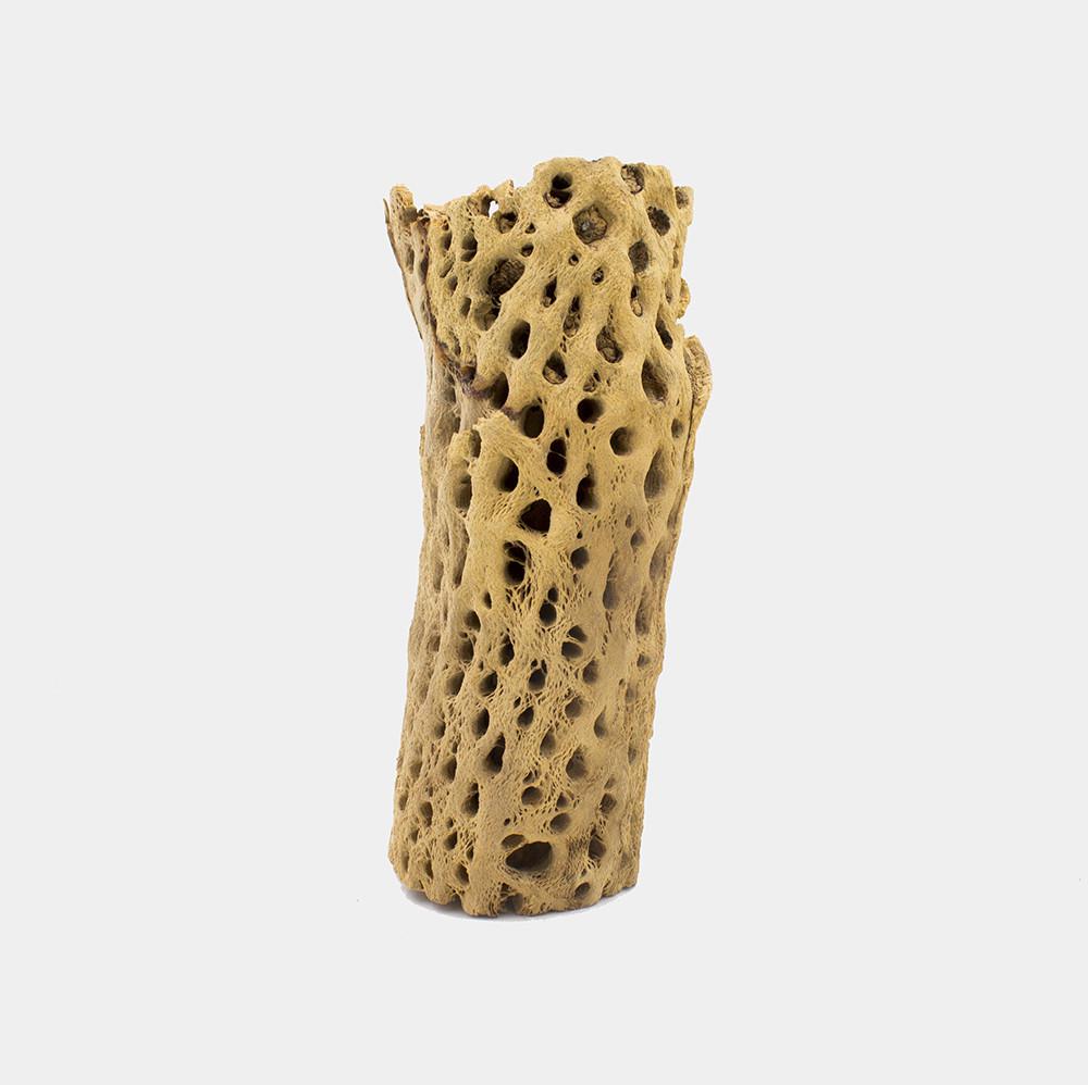
To build my robot arms I stole an idea from one of my Make Santa Fe cohorts and generated a cutout pattern -- to reduce weight, certainly NOT for any decorative purpose whatsoever -- from a photo of cholla cactus trunks which I stole from an online aquarium supply store -- ??? who knew fish like to hide in cholla remains ???.
cholla chunk
Some detail about this process might prove useful to our future selves...
I found a decent photograph online and a web site that does "free" Raster-to-Vector conversions, if you have good images. I don't know how scammish this site is but, NoThanks-ing various pleading messages got me to where I could use it to convert images to vector outlines in DXF format.
Strangely it worked well. I massaged the vector files to be useful to my purposes -- removing decorative and practical bits of material from some robot arms in order to slightly reduce their weight.
cholla2orig*.jpg are the original and P-shop massaged images.
cholla3.* are the resulting vector data, and a jpg image thereof.
cholla3ed.* are my editing of that data for use on the robot arms.
The non-orig JPG images are for reference purposes, and the .dxf files are what you need to load into a vector editing or cutter driving program. The DXF files may have bizarre scales -- the conversion came out to look like it was 64 feet wide -- so pay attention to the sizes... The .CAD files are the native format for the ancient drawing program I have.
Combining all the data, I cobbled together designs for five arms of different lengths using the different motors. So. Here. After all the measuring and converting is a motor with gears, mounted in a laser-cut robot-arm-like contraption:
arm with motor and gears
And the DXF files: Long arm and Shorter arms. (Note that these files are preliminary and some finessing is still TBD.)
<EDIT 10/21/18> I think I fixed the files -- added spacers and other odd bits to the "shorter" one -- but still, check the mechanical hole sizes: Long arm and Shorter arms.</EDIT>
I cut the arms using the MSFe Zing laser cutter, which has some quirks. Chief among these for purposes of mechanical design is a somewhat variable kerf and a reasonable but unmentioned assumption about circular hole sizes. Fortunately the centering of holes is pretty spot on and the size assumption is that the drawn hole size is an ID -- so holes come out just about as you would expect. However, if one is cutting out round plugs, the kerf needs to be considered. Thus YMMV when using my files to try to make a copy of my arms, and test runs are advised. Also, judicious reaming and taping of holes is indicated during assembly.
More discussion of the design and gear linkage will follow...
And so, a couple months ago I came down with a (tiny) fit of organizing fever and cleared up a small portion of a pathway in (one of) my massively parallel parts storage areas. I found some crappy motors I had gotten (cheap) from a surplus place that I had attempted to make into a 2-d swinging robot arm, to make even some small progress on the big proposal.
They didn't work worth a damn:
picture of crappy motors
But, out of curiosity, I found a sketch of my intentions in an old notebook from 2014 (where you can clearly see why I do not practice drawing and painting as a profession):
picture of robot arm crappy drawing
I got to thinking that maybe I could re-start the whole project by actually spending money to get motors and components that might work. (Over this course I realized that I could spend $200 on oysters and gin and have a fine time with friends for an evening, or I could spend -- well, more, but in the ballpark -- on motors and gears, and get in a week or two of mostly enjoyable fiddling around before discovering that things weren't going to work; so, bang for buck over hours this is a way more economically efficient alternative.)
There ensued a couple weeks of web surfing trying to figure out what "hobby servo" motors to get, even though I already have about 50 random ones.
There are a number of vendors.
Each has around 100 choices.
The choices are mostly incommensurate.
Comparing across the sources, and sometimes within a single source, is problematic. Plus there are around 10 different output shaft "spline" configurations, that are often not even specified in the literature. I finally realized that I had to stick to one source (servocity.com, the high price spread, but has reasonably complete spec sheets). And this lead me to realize that I had only two choices of splines because they were the only two that had available matching gears to be attached. So I got an assortment of the highest power motors with the same matching splines, and a buncha gears:
servo boxes
Then, waiting on UPS Ground cheap(er) shipping, I thought I would just go ahead and design the mounting brackets and all. Thus I found that not even the motor manufacturer has mechanical drawings of their products (I did find one 3d rendering of one that I could rotate around in virtual space, which was kinda fun). Of course, one of the main things one wants to know when designing mounting plates for geared mechanisms is: How far is the output shaft from the mounting holes?
So. After the motors arrived I managed to measure and estimate the necessary and the gears seem to mesh OK. Just in case, here is my DXF drawing of the Hitek HS-225, HS-645, HS-755, and HS-805 motor mounts from which you may be able to extract relevant measurements. These are laid out to mesh two 32 pitch gears:
40 Tooth 1.250" Pitch diameter C1 Spline mount on the motor
20 Tooth 0.625" Pitch diameter plain bore on the mating arm
Anyway. A few years ago the LA County Museum of Art (LACMA) re-started an Art and Technology program that had slipped under the waves in the early 70's. So I hacked and hewed a proposal to make a set of robot arms that Learned to Dance. I called the work Variations For as a pun on John Cage's, Variations IV, the canonical recording of which was made in LA in the mid-60's
tldr; The arms solved the problem of knowing their own orientation and could just as well use the same sort of algorithms as my RoboCars to create a sequence of motions -- Teach Themselves to Dance -- AND could be influenced by viewer input via video. Plus the LACMA program was set up to put artists together with technological support -- which I could, certainly, use. That and money to pay for stuff...
Due to my obvious lack of Charm, Cachet, Credential, and Competence, they wisely declined my proposal. It was however a high point of my applying for things because I got BOTH an acknowledgement of receipt AND a politely encouraging rejection letter.
Funnily(?) enough. A couple years ago I ran across another artist who had subsequently applied for the same program with a proposal (in my loose interpretation) to make video game characters able to determine their own next moves rather than always having pre-programmed responses. Since he clearly was in possession of all the above 'C' qualities his project was accepted, and I noticed a recent announcement of some show of something in progress, up on which I did not follow.
Back in pre-history I had a job doing robotics research which lead me to make some small autonomous vehicles that, thanks to my friend Tori's support in showing something at her Dactyl space in Soho, developed a sequence of motions for themselves -- taught themselves a dance step.
Here's the whole presentation from a time when the internet sort of worked for video, which it now does in a completely differently-abled way (I think the video files are still there but they are in Quicktime which seems to have been disappeared):
tldr; Each robot had a set of motions it could do -- forward, backward, and turns. It would pick a partner and each would select a motion and then adjudicate who's movement to execute. This would make that motion more likely to be selected, by both partners, in future situations. Then they would pick a new partner and repeat the exercise until, eventually, all five of the vehicles would be performing the same sequence. This was programmed using a Stochastic Finite State Automata, which is a fine state of affairs if you are not jargon enabled.
Unfortunately, I (they) had no way of knowing where each vehicle was and which way it was facing. So the net result still looked a bit of a jumble. But. Here is the U-Tub money shot from when "they" all happened to synchronize (at https://youtu.be/slfprpe848s):
I tried to fix the position insensitivity a couple times but eventually lost interest due to many of my pre-existing conditions.
Funny(?) aside. Now, ten or so years later, it appears that Urs Fischer has (hired folks to) solve this problem using a set of office chairs, as displayed at the Gagosian Gallery in Chelsea: