If....
* Jeff Koons can afford an atelier of assistants to polish his balls;
* Urs Fischer can hire someone to construct a set of autonomous office chairs;
* Mauricio Catellan can be praised for his Duchampian wit, a century on;
* Darren Bader can get a warm review in the Times for his re-heated thoughts;
Then....
It seems that even the ideas of post-post-modern artists' are of little utility.
Therefore....
Along with no longer producing anything of intrinsic value, I should also outsource the conceptualizing. Surely there are artists in other countries who can have ideas much more economically than me?
After that, given its glaringly short supply in the developed world, I might as well suspend my judgement as well.
So, from here on in, just assume that, if I had thought it was worth the effort, I would have done it.
Already....
Showing posts with label art. Show all posts
Showing posts with label art. Show all posts
Saturday, January 4, 2020
Wednesday, June 19, 2019
and for completness sake
A short Variations Too documentation video from Currents 2019 in Santa Fe:
(many thanks to my spokes-model, Raina Wellman!)
Monday, April 29, 2019
Variations Too -- The Program
I seem to have (finally) come to a rest in the development cycle of the Variations project so I thought I should post the actual Arduino code, for completeness sake....
VariationsToo.zip
You will also need all (or most of) my previously described libraries:
schipArduino.zip
I had to give up on the HCSR04 sonar distance detector because it was unreliable, noisy, and sensitive to vibrations when the arm servo motors were running. I replaced it with my old favorite, the GP2Y0A02YK (or equivalent) IR distance sensor that triggers out at about 2 meters. This only needs an ADC channel to interface, so it's a lot simpler anyway.
Variations Too will be in:
CURRENTS NEW MEDIA 2019
in Santa Fe, NM, from June 7 - 23. So come on by!
...You and I both have to wait until the piece is installed in the gallery before I can make a decent video because I have run out of room for clean backdrops in my home/studio...
...You and I both have to wait until the piece is installed in the gallery before I can make a decent video because I have run out of room for clean backdrops in my home/studio...
Thursday, January 31, 2019
Some Driveline Enhancements
Variations Too, again
While doing limited in-camera demos I found that the Variations second arm linkage just tore itself apart pretty consistently. This was due to there being nothing but a bit of stickyness holding the axle into the arm. I originally used two pins through the whole sandwich to keep the gear from spinning, but I didn't have anything really holding the layers together, and there was too much torque for the sticky to manage.
This has, perhaps, been remedied:
 |
| Improved(?) axle mounting |
After the arm was all re-assembled, I drilled a hole longitudinally through the circular backing plate and the axle, and glued a 1" long by ~1/32" diameter nail into the hole. This of course requires solid drill press, or mill, mounting and careful attention to not breaking the (@$!@#) miniature drill. Here you can also see the two pins (little brass brads, also about 1/32" dia) that pierce the entire sandwich to prevent the gear from spinning on it's own.
Compare to the previous layout, where the above photo is looking straight on from the bottom:

I did this for the two lower arm linkages and made the executive decision that the torque on the smallest, upper, arm did not merit the extra effort. YMMV...
So.
I think this may be the end of the mechanical portion of our time together, save perhaps for cable routing which is still rather ad-hoc.Tuesday, November 13, 2018
Sonar! The HCSR04 Library
For Variations Too I need some kind of distance sensor to see if there is anyone watching and how interested they might be. For the 'real' Variations I am planning to use a video camera and image processing, but this is the kiddie version.

See the data sheet here.
But, if you've been reading along, you know that the Servo motor control library is also a big fan of Timer 1 and thus that acre of digital real estate is no longer available. So I had to reinvent the wheel using a different mechanism with Timer 2 which has only an 8 bit resolution and no external count input.
Therein lies the HCSR04 library in my code bolus.
It uses three interrupts (you are surprised?), two from Timer 2 and one from an external pin change signal. The counter is run with the maximum pre-scale of /1024, giving a 64 micro-second resolution which is not quite as fine as one would like, but it turns out that the sensor itself is not quite as fine as one would like either, so it sorta works out. It counts the timer overflow interrupts to add 4 more bits to the timing range, which is somewhat more than enough to detect the SR04's no-signal failure signal.
Two digital pins, and power, are connected to the sensor. One pin is the Trigger output which can be any available digital output pin. It sends a short positive pulse, where the falling edge starts a sonar sample cycle. The other is the Ping input pin which goes high from the end of the sonar ping until it gets an echo response -- or for a loooong time if it misses the echo (more below). The Ping input currently has to be Arduino Pin 2 or 3 -- because I couldn't make sense of the doc for attachInterrupt(), I think one can use other pins but the code will need a light re-wanking.
HCSR04();
/** initialize the HC-SR04 sensor pins and timer interrupts
** leaves all the interrupts disabled
** use SR04.startPing() to start a sample cycle **/
void init( uint8_t trigpin, uint8_t pingpin );
/** Start a sensor ping cycle
** turns on TRIGPIN and enables interrupts
** Presumes that SR04init() initTimer2() have already been called. **/
void startPing(void);
/** return true if there is a new distance value available
** will clear itself, so a second call will return false... **/
bool available(void);
/** return the last distance value from the sensor
** if it's 0x0000 we didn't get anything... **/
int16_t getDistance(void);
After the class is initialized, a call to startPing() will send a trigger pulse and wait patiently for the results. Under the covers, the Trigger output pin is set high and Timer 2 is started, a count interrupt is fired after two counts and used to turn off the Trigger pin, thus starting the Ping cycle. When, and if, the timer wraps around on 256 64uS counts (~16.4mS), the overflow interrupt fires and a global status variable is incremented -- this allows for an extended count range, in this case up to 4 bits or x16. When the Echo input pin goes low, the input pin interrupt fires, all the counts are counted up, and the available() interface will signal by returning true -- just once. When that happens getDistance() can return something useful.
The speced range of good distance data is from about 10 to 360 (in 64uS increments). I did not subtract the two-four initial trigger counts so you can do that if you want a bit more accurate close range measurement. If you multiply the count value by 1.1 you can get fairly close to the actual distance in CM.
However in a spot check, I did not get reliable distance counts beyond about 180, i.e. 200cm, so YMMV. Also it jumps around, failing for a number of cycles before coughing up an occasional good value.
A note on the bad values.... If there is no ping return received the sensor just keeps going until it gets tired. The spec says this should be 38mS after the trigger, but the reality seems to be closer to 150mS. So when there is nothing to sense, the time between cycles is quite long. When the ping goes missing, available() will eventually return true and the getDistance() method will return 0 -- this just makes it easier to see on a data plot. Should everything fail -- the counter will just keep counting up to it's 16x maximum and getDistance() will return 0x8000 (a negative number).
For a usage example look to the test.ino file. Connect the sensor to Gnd and +5v power, Trigger to Pin 2, and the Ping to Pin 3. Create a global HCSR04 object and call init(pinT, pinP) in setup(). Then call startPing(), available() in a loop, and getDistance() when available returns true.
So...
I thought I had it all worked out because I've used this cheapo, err, inexpensive, HC-SR04 (aka 19605-UT) ultrasonic sensor, from mpja.com amongst, in other projects using my MSCapture library which turns Arduino Pin 8 into a Timer 1 counting input -- remind me to rant about this sometime, especially since my library is perfect for grabbing IR remote control signals -- but for now.
See the data sheet here.
But, if you've been reading along, you know that the Servo motor control library is also a big fan of Timer 1 and thus that acre of digital real estate is no longer available. So I had to reinvent the wheel using a different mechanism with Timer 2 which has only an 8 bit resolution and no external count input.
Therein lies the HCSR04 library in my code bolus.
It uses three interrupts (you are surprised?), two from Timer 2 and one from an external pin change signal. The counter is run with the maximum pre-scale of /1024, giving a 64 micro-second resolution which is not quite as fine as one would like, but it turns out that the sensor itself is not quite as fine as one would like either, so it sorta works out. It counts the timer overflow interrupts to add 4 more bits to the timing range, which is somewhat more than enough to detect the SR04's no-signal failure signal.
Two digital pins, and power, are connected to the sensor. One pin is the Trigger output which can be any available digital output pin. It sends a short positive pulse, where the falling edge starts a sonar sample cycle. The other is the Ping input pin which goes high from the end of the sonar ping until it gets an echo response -- or for a loooong time if it misses the echo (more below). The Ping input currently has to be Arduino Pin 2 or 3 -- because I couldn't make sense of the doc for attachInterrupt(), I think one can use other pins but the code will need a light re-wanking.
 |
| HC-SR04 signals |
The library class has these methods:
/** default constructor **/HCSR04();
/** initialize the HC-SR04 sensor pins and timer interrupts
** leaves all the interrupts disabled
** use SR04.startPing() to start a sample cycle **/
void init( uint8_t trigpin, uint8_t pingpin );
/** Start a sensor ping cycle
** turns on TRIGPIN and enables interrupts
** Presumes that SR04init() initTimer2() have already been called. **/
void startPing(void);
/** return true if there is a new distance value available
** will clear itself, so a second call will return false... **/
bool available(void);
/** return the last distance value from the sensor
** if it's 0x0000 we didn't get anything... **/
int16_t getDistance(void);
After the class is initialized, a call to startPing() will send a trigger pulse and wait patiently for the results. Under the covers, the Trigger output pin is set high and Timer 2 is started, a count interrupt is fired after two counts and used to turn off the Trigger pin, thus starting the Ping cycle. When, and if, the timer wraps around on 256 64uS counts (~16.4mS), the overflow interrupt fires and a global status variable is incremented -- this allows for an extended count range, in this case up to 4 bits or x16. When the Echo input pin goes low, the input pin interrupt fires, all the counts are counted up, and the available() interface will signal by returning true -- just once. When that happens getDistance() can return something useful.
Results
The speced range of good distance data is from about 10 to 360 (in 64uS increments). I did not subtract the two-four initial trigger counts so you can do that if you want a bit more accurate close range measurement. If you multiply the count value by 1.1 you can get fairly close to the actual distance in CM.
However in a spot check, I did not get reliable distance counts beyond about 180, i.e. 200cm, so YMMV. Also it jumps around, failing for a number of cycles before coughing up an occasional good value.
A note on the bad values.... If there is no ping return received the sensor just keeps going until it gets tired. The spec says this should be 38mS after the trigger, but the reality seems to be closer to 150mS. So when there is nothing to sense, the time between cycles is quite long. When the ping goes missing, available() will eventually return true and the getDistance() method will return 0 -- this just makes it easier to see on a data plot. Should everything fail -- the counter will just keep counting up to it's 16x maximum and getDistance() will return 0x8000 (a negative number).
For a usage example look to the test.ino file. Connect the sensor to Gnd and +5v power, Trigger to Pin 2, and the Ping to Pin 3. Create a global HCSR04 object and call init(pinT, pinP) in setup(). Then call startPing(), available() in a loop, and getDistance() when available returns true.
So simple. Even I could do it!
Sunday, November 11, 2018
SCHervo Library and ServoTask
I made some of my usual "improvements" to the standard Arduino Servo motor control library. Building on my Task Scheduler I've added a speed control, so the time it takes a Hobby Servo motor to move from it's current position to a new one can be controlled over a fairly large range.
My SCHervo library comprises a cleaned up and (hopefully accurately) commented original version, with the usual Schip Secret Sauce additions. A simple addition is a turnOff() method which just shuts the motor off so it isn't using power trying to hold a position (or speed) that you don't care about. The more complicated addition is a Task to update the position -- and thus speed -- of each motor over a fixed interval. This allows the motor to transit in pseudo-continuous increments over a fairly extended period (up to about 1 minute). The motion is initiated using the startMove() method, can be monitored with ready() which returns TRUE when the motor has (just about) reached its new position, and stopMove() to make it stop at any time in-between.
And here is a better description.
Another thing to remember is that the motor doesn't just suddenly go to the new position, but has a finite slew rate, generally something like 60 degrees in 200mS. This works out to 5 or 6 degrees in each 20mS refresh period, which is also the fastest the motor can get any new position input.
So... If we change the delivered pulse width in every 20ms period we can control the motor's angle change speed. And that's what the ServoTask() does. Recall that all of the 8 controllable motor's pulses are sequential, stacked such that the next starts after the previous finishes, and when they are all done there is a slack period until the 20mS refresh times-out. The ServoTask() is posted from the timer interrupt service routine at the beginning of the slack period, and -- in theory -- it will execute and update the desired pulse widths for the next period.
When a motor is started using startMove( endPosition, time, offFlag ) the code calculates how many micro-seconds should be added to the current pulse width in order to transition from the starting to end positions in the given amount of time. I got a little tricky and used a Fixed Point calculation with 3 bits of "sub-precision", to handle longer moves, but that's just between you, me, and the code.
So what do you do when you would like to maintain some fractional components in your arithmetic? Why Fixed Point of course! I'll leave it to wikiP to explain: https://en.wikipedia.org/wiki/Fixed-point_arithmetic
The tldr; of it is that you shift int values up by a consistent number of bits, do your arithmetic, and then shift them back down when you want to get a nice truncated integer again. This needs to be done judiciously because you only gain the precision of the up-bit-shift, and this number of bits is removed from the range of your values. In the case of my 3bit FixP values using a 16bit int, you get a precision of 1/8th or .125 in decimal and a range of +/- 0 to 4096 (12 bits plus sign). Which turns out to be just fine for calculating the micro-second values needed by the servos.
TBD
Note that the old-fashioned Servo.write() interface does not provide a way to determine when the motor is (almost) done moving. My startMove() method tries to account for the slew rate during fast motions by adding some guess at the amount of time needed. But this runs into a bit of trouble from the internal motor controller, which usually treats smaller moves as slower changes (this is how you are sometimes able to get speed control from motors that have been modified for continuous rotation). This behavior also slows the motor down when using the ServoTask() incremental stepping, so the internal how-long? guess is not always right.
I could do a little more hacking to better integrate faster slews -- it shouldn't be THAT hard, heh -- and this would also eliminate the need for the 'regular' write() interface (or draw it into the fold) such that, in all cases, the ready() method will really tell you when the motor is done moving
It did take some reverse engineering...
The regular Servo library uses Timer 1 (on the 'standard' Arduino ATMega 328's -- I haven't worked this out all for other chips) to operate up to 8 (they say 12 but I think it gets a bit slippery after 8) servo motors. It does this by sequencing the ON pulses for each motor, one-after-the-other, which is pretty slick. Or would be IF the authors had mentioned what they were doing someplace. There's very little internal documentation -- Comments, Please! -- in the code. But I persisted.My SCHervo library comprises a cleaned up and (hopefully accurately) commented original version, with the usual Schip Secret Sauce additions. A simple addition is a turnOff() method which just shuts the motor off so it isn't using power trying to hold a position (or speed) that you don't care about. The more complicated addition is a Task to update the position -- and thus speed -- of each motor over a fixed interval. This allows the motor to transit in pseudo-continuous increments over a fairly extended period (up to about 1 minute). The motion is initiated using the startMove() method, can be monitored with ready() which returns TRUE when the motor has (just about) reached its new position, and stopMove() to make it stop at any time in-between.
But first lets review just this much: How do Servos work?
The basic idea is that you send the motor a positive pulse every 20mS (big T in the picture below), where the width of that pulse (little t) is proportional to the position one wants the motor shaft to take -- usually defined as from 0 to 180 degrees. Each degree position translates to a pulse width, which generally varies from 500 to 2500 micro-seconds, where 1500uS is a nominal 90 deg center position. Each motor is a bit different in it's range and widths, but that's the general scope.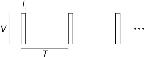 | |
| picture of a servo drive pulse train |
Another thing to remember is that the motor doesn't just suddenly go to the new position, but has a finite slew rate, generally something like 60 degrees in 200mS. This works out to 5 or 6 degrees in each 20mS refresh period, which is also the fastest the motor can get any new position input.
So... If we change the delivered pulse width in every 20ms period we can control the motor's angle change speed. And that's what the ServoTask() does. Recall that all of the 8 controllable motor's pulses are sequential, stacked such that the next starts after the previous finishes, and when they are all done there is a slack period until the 20mS refresh times-out. The ServoTask() is posted from the timer interrupt service routine at the beginning of the slack period, and -- in theory -- it will execute and update the desired pulse widths for the next period.
When a motor is started using startMove( endPosition, time, offFlag ) the code calculates how many micro-seconds should be added to the current pulse width in order to transition from the starting to end positions in the given amount of time. I got a little tricky and used a Fixed Point calculation with 3 bits of "sub-precision", to handle longer moves, but that's just between you, me, and the code.
However ... Fixed Point
If you know me, you know, I can't resist a few, more, comments. The Arduino using an ATMega 328 has no hardware support for Floating Point math. Should you make the mistake of including a float value in your program the linker will pull in about 1kB of code to support it. And further, should you blunder into actually using the float in a math-like-way, the result will take (relatively) forever. It's actually even worse, as the ATMega has only a small set of 16bit integer Multiply instructions (along with ADD and SUBTRACT) and NO Divide at all.So what do you do when you would like to maintain some fractional components in your arithmetic? Why Fixed Point of course! I'll leave it to wikiP to explain: https://en.wikipedia.org/wiki/Fixed-point_arithmetic
The tldr; of it is that you shift int values up by a consistent number of bits, do your arithmetic, and then shift them back down when you want to get a nice truncated integer again. This needs to be done judiciously because you only gain the precision of the up-bit-shift, and this number of bits is removed from the range of your values. In the case of my 3bit FixP values using a 16bit int, you get a precision of 1/8th or .125 in decimal and a range of +/- 0 to 4096 (12 bits plus sign). Which turns out to be just fine for calculating the micro-second values needed by the servos.
TBD
Note that the old-fashioned Servo.write() interface does not provide a way to determine when the motor is (almost) done moving. My startMove() method tries to account for the slew rate during fast motions by adding some guess at the amount of time needed. But this runs into a bit of trouble from the internal motor controller, which usually treats smaller moves as slower changes (this is how you are sometimes able to get speed control from motors that have been modified for continuous rotation). This behavior also slows the motor down when using the ServoTask() incremental stepping, so the internal how-long? guess is not always right.
I could do a little more hacking to better integrate faster slews -- it shouldn't be THAT hard, heh -- and this would also eliminate the need for the 'regular' write() interface (or draw it into the fold) such that, in all cases, the ready() method will really tell you when the motor is done moving
But. Otherwise. You should be able to just go ahead and use it now...
Sunday, November 4, 2018
Analog to Digital!
When Worlds Collide
Another "feature" of my new improved Arduino architecture is ADC access...Interrupts
Due to my antipathy for busy waiting -- rather than looking busy I'd prefer to just not do anything -- I implemented an interrupt driven ADC interface.In the standard Arduino system, calls to analogRead() execute a conversion in place (and block for the time it takes to complete). In my new improved system, conversions free run at the slowest rate available on the Atmega chip in the "background". And the standard interface calls are redefined to just return the most recent value from the requested channel. This takes a bit of processor -- not user -- attention but makes the getting of values almost immediate. If one is doing data acquisition one is probably getting ADC values fairly frequently, so it's likely the number of instruction cycles tradeoff is not a big issue.
The number of channels accessed by the background conversion cycle can be set in the schip_analog.h file. Usually 4 is sufficient, but a total of 8 are available on many Atmega chips. Note that I2C communication uses A4 and A5, so if you need them there is a provision for skipping those channels in the sample loop.
ADC Task
A second feature of my interrupt driven conversion code is an averaging algorithm which squeezes 64 samples into one smoothed 8-bit value. This allows a lot of noise and nonsense to be filtered out of the individual conversions. Specifically, for instance, 50-60Hz hum... These values are accessed using analogReadAvg() which will return the most recent average for each channel.When enabled, the averaging cycle also creates a reasonably timed -- in the multi-millisecond range -- repetitive sample cycle. At the end of each averaging period the ADCTask( num_channels ) function is posted to the task scheduler, which will then execute it very close to the time that all the channel averages become available. The exact timing of this posting is determined by the number of ADC channels being converted:
For the Arduino Uno and PRO-Mini with a 16Mhz Atmega 328, the ADC prescale is set at the maximum 128 clocks, and a single ADC conversion takes about 110uS
With NUM_ADCCHANNEL set to 4:
A four channel ADC cycle takes about 450uS (2222Hz sample rate) so 64 conversion cycles takes about 29mS.
The Leonardo seems to be a bit slower:
A single ADC conversion takes about 120uS, and a four channel ADC cycle takes about 480uS (2085Hz sample rate) so 64 conversion cycles takes about 30.7mS.
With NUM_ADCCHANNEL set to 8 and SCHIPSKIPI2C defined for a total of 6 channels:
A six channel ADC cycle takes about 660uS (1515Hz sample rate) so 64 conversion cycles takes about 43mS.
Audio Data
A tertiary feature -- not used in the Variations context -- is a double buffering scheme for ADC channel 0 which allows 64 10-bit samples to be collected into a local buffer. When the buffer fills it's address is put into the global pointer SchipBUF0, from whence the user can get and manipulate the data. While the user is playing with buffer one, a second buffer is being filled and it's pointer is alternately placed into SchipBUF0. So if you can keep up, you can do some audio processing at a reasonable sample rate. See the SoundBit for an example.The time between buffer updates and the actual rates for various configurations are listed as the conversion-cycle and sample rate above.
'Kernel' hack
In keeping with not being able to leave anything alone I have made some insertions in the core "kernel" ADC code to remove the old-fashioned analogRead() function. This is included in the "cores" directory of the code bolus. It is not strictly necessary, but is sufficient to avoid confusion and save a few bytes of program memory.setup()
In all cases, when using the new-improved-interrupt code one needs to kick things off by calling analogRead( n ) once in the setup() method. This will usually return 0, so the value should be ignored. Too bad, in the old world we could have used the value as a random number seed but now have to find some other workaround for that.More Anon.
Friday, November 2, 2018
Task Scheduling
At the bottom of my new-improved-code pile is the scheduler library which makes possible a semblance of non-pre-emptive multi-tasking. It maintains a list of Task functions to be executed with a single argument (which can be cast to be an arbitrary pointer) and the number of milli-seconds in the future that the function should be fired off. Using this system you will never use the busy-waiting delay() again. It is contained in the schip_scheduler library, and optimally linked through the Arduino cores 'kernel' code. See those directories in my code bolus ref'd in Software Architecture.
Task functions have the signature:
typedef void(*PFV)(uint16_t); // pointer to a function for task list
which looks like this when you define one:
void myTask( uint16_t arg ) { return; }
By default, the function list has 8 entries and attempt to enter more will fail with an error code. The size can be changed in the header file with:
#define USE_NumTasks 8
There are four user entry points to the library:
void initScheduler(void);
initScheduler() should be called in the setup() method before any tasks or task related interrupts are posted or enabled.
void scheduler(void);
scheduler() should be called in the loop() method, and may be the only function there -- modulo a serial message checking block if one uses such -- see subsequent blogging about message Tasks. This is where the busy-waiting is concentrated, but it is only waiting busily when there is nothing else to do.
A task can be inserted into the list using;
int postTask( uint16_t ticks, PFV func, uint16_t arg );
where 'ticks' is the number of milli-seconds in the future that the task should be executed, 'func' is the task method to execute, and 'arg' is an arbitrary 16 bit sized value to pass when executed, ala: func(arg). A post call might look like this:
postTask( 100, myFunc, 0 );
It will return the task's index in the list, or -1 if it fails.
An executing task may call:
void repostTask( uint16_t ticks, uint16_t arg );
to put itself back into the scheduler's list with the given execution delay and argument value.
There is, as of now, no removeTask(). Everything in the list gets executed when it's time comes...
A user task should not run for a long time and should never call delay() or other blocking functions as this will prevent other tasks from running. If the task is going to do a lot of nonsense it should be broken into smaller functions that post each other in succession. This allows 'background' tasks, such as ADCTask() and ServoTask() to get an execution in edgewise. All tasks run to completion in "user memory space" so there are minimal worries about concurrency. However interrupt service routines can both interrupt and post tasks during execution, so some attention should be paid to shared variables in those contexts.
There are two versions of the scheduler library. One is fully in the "user program space" and uses millis() to calculate elapsed time between calls. This has a bit more overhead and can be less precise in it's execution delays. The 'real' one can be hacked into the Arduino cores "kernel" and uses a callout from the milli() tick interrupt to manage the times in the task execution list. It is somewhat more efficient but the drawback is you have to hack it into each kernel version as it comes off the press. There is some discussion in the library header file and in the cores/readme.txt about how to install it.
A secondary advantage to the "kernel" version is that it can contain another callout to a user function on every milli() tick. And THIS can be used to implement, e.g., a stepper motor step sequence. See SCHIPTICK in the files....
Next up: ADCs
Thursday, November 1, 2018
Software Architecture
The low level controller in the Variations Too project is an Arduino, beloved by LED Flashers around the world. But my last actual job title in the Software Industrial Complex was Extensibility Architect (...see how well that went here...) so I can't leave things alone without extending upon them. And the Arduino system is badly in need of some Software Architecture. Since it's simple enough, in most respects, that I can almost understand it, that's what I've been doing by fits and starts lately.
First, there's a lot of busy-waiting going on. The Analog to Digital Converter (ADC) code just starts a conversion and sits there waiting for it to complete. This is not so bad as it usually comes through in a tenth of a millisecond, but that's about 400 instruction cycles that could be used for doing something useful.
Then... delay() is the favored way to make something happen sometime in the future. This is just a bad idea in a system that might be responding to a buncha stuff in a realish time frame.
And. Then. Speaking of responding. The "usual" way to do responsible data acquisition is to sample at some fixed rate. There is no provision for doing that in the system as it is constructed.
Plus. Communication. One often wants to send and receive messages from the rest of the computing planet in some reliable manner. Unfortunately the Serial interface has hidden it's underlying structure and parsing mechanisms such that this is difficult. Doubly impossible if one needs to implement a message format that contains framing, headers, and/or checksums, which might, for instance, be of use in less than predictable mediums like radio.
http://www.etantdonnes.com/DATA/schipArduino.zip
Details at 11.
First, there's a lot of busy-waiting going on. The Analog to Digital Converter (ADC) code just starts a conversion and sits there waiting for it to complete. This is not so bad as it usually comes through in a tenth of a millisecond, but that's about 400 instruction cycles that could be used for doing something useful.
Then... delay() is the favored way to make something happen sometime in the future. This is just a bad idea in a system that might be responding to a buncha stuff in a realish time frame.
And. Then. Speaking of responding. The "usual" way to do responsible data acquisition is to sample at some fixed rate. There is no provision for doing that in the system as it is constructed.
Plus. Communication. One often wants to send and receive messages from the rest of the computing planet in some reliable manner. Unfortunately the Serial interface has hidden it's underlying structure and parsing mechanisms such that this is difficult. Doubly impossible if one needs to implement a message format that contains framing, headers, and/or checksums, which might, for instance, be of use in less than predictable mediums like radio.
On the other hand
I was making amazing claims about the Arduino system, such as, "It just seems to work!" -- in comparison to a previous ATmega based development system, constructed by grad students that needed thesis topics, I used, lets just say, 20 years ago, where my strongly held belief was that NO ONE knew how the build system worked, such that the way to get it running was to reinstall different versions until a compile stuck to the wall. But. Of course. The one time I tried to teach a class using Arduinos, three of the six students had varying levels of failure, from port configuration (on a Mac, so, well, yeah, sure...) to execution failure (on what appeared to be a garden variety Widows machine). So I've forsworn further involvement of that nature.But I woolgather...
Here's the latest bolus of my improvements to the world:http://www.etantdonnes.com/DATA/schipArduino.zip
Details at 11.
Sunday, October 21, 2018
Variations Too -- (semi-final) assembly
Semi-final, in theory, as I might get around to integrating a rasPi with video detection to run some smarter pattern development and to be able to communicate amongst a group of these guys in order to pass steps around the dance circle. Thus implementing Variations 3.20. Someday.
But for now....
I went for a weighty base made of a 20" long piece of 6x2x1/4" steel U-channel that I had lying around in another of my massively parallel storage areas and drilled mounting holes (or mis-drilled in some cases) for everything I could think of:
Here's all the sensor and controller wiring before the motor assembly was mounted:
The controller is an Arduino Pro-Mini mounted on a carrier board of my own design that provides powered connectors for most I/O and some other accessory features. If you're wondering, here are the files (the design is done using the ExpressPCB.com proprietary software because I ABSOLUTELY REFUSE to use the popular Program Which Shall Not Be Named):
RoboAssist files
Wiring the motors around the arm rotation points is ad-hoc, and a Royal PITA. I left enough slack at each junction to allow rotation without dragging the wires into the gears. It would have been easier if I had just bitten the bullet and bought servo extension cords. Maybe.
So here's the final:
And a little demo run:
Now on to the software....
But for now....
I went for a weighty base made of a 20" long piece of 6x2x1/4" steel U-channel that I had lying around in another of my massively parallel storage areas and drilled mounting holes (or mis-drilled in some cases) for everything I could think of:
 |
| top of the heavy steel base |
Here's all the sensor and controller wiring before the motor assembly was mounted:
 |
| wiring underneath |
The controller is an Arduino Pro-Mini mounted on a carrier board of my own design that provides powered connectors for most I/O and some other accessory features. If you're wondering, here are the files (the design is done using the ExpressPCB.com proprietary software because I ABSOLUTELY REFUSE to use the popular Program Which Shall Not Be Named):
RoboAssist files
Wiring the motors around the arm rotation points is ad-hoc, and a Royal PITA. I left enough slack at each junction to allow rotation without dragging the wires into the gears. It would have been easier if I had just bitten the bullet and bought servo extension cords. Maybe.
So here's the final:
 |
| Variations Too |
And a little demo run:
Now on to the software....
Friday, October 19, 2018
Variations Too -- taxonomic exegesis
Lemme take a little timeout here to explain my naming scheme.
As I mentioned earlier, the ur-text for all this was my proposal for an installation called Variations For, which was a pun on the 1960s John Cage piece Variations IV. Get it? Ha. Ha.
Failing to make headway on that, for lack of tens of thousands of dollars and square feet to house and feed Industrial Robots, I realized that I might be able to make my own set of simpler robot arms along the lines of the sketch in the first of these blog entries. That also faltered along technical and financial lines.
Recently, working on reducing my horizons, it occurred that I might at least be able to make ONE damn robot arm and get it to do something. Thus came to be Variations Too. You may have realized this is a pun on Two, as well, as meaning, Also. Ha. Ha.
So. Should VToo work, I will have a base model from which to construct four more. (For, more, still with me? Ha. Ha.) And that will be the basis for developing the real idea of making a set of robots that choreograph a dance together under their own direction -- even if it is still in only two dimensions. That version I would call Variations 3.20, because it is the first 80% of Variations For, where the last 80% is "just" programming the industrial robots. That's an engineering joke. Ha. Ha.
Anyway.... Next time, some more about the final construction.
Thursday, October 18, 2018
Variations -- on a linkage
Here's another video of the Variations Too robot arm in action:
For aesthetic reasons I fixated on being able to get the arms to fold up in the "parked" position as seen at the beginning and end of that video. Since almost all hobby servos only travel around 180 degrees, and ones that do travel further are more expensive, less powerful, and slower, I needed a 1::2 rotation step up; and, to maintain the sense of servo position it needs to be a timing belt or gear. Since timing belts are even harder to come-by, gears were the choice. Using a gear linkage also isolates the weight of the driven arms from the bearings in the motors themselves. It also allows the motors to be used as sorta-counter-weights, being mounted on the opposite side of the rotational bearing from the main weight of the arm. At this writing it remains to be seen how this all plays out, but here's a picture of the mechanism:


The arms are made from two different thicknesses of plexiglas, as can be somewhat discerned from the linkage photo. The lowest arm is .170" and the others are .120". In retrospect, for rigidity, I might use the thicker material for the second lowest arm as well.
The motors each have different 'vertical' spacing from the mounts to where a gear might be conveniently centered on the spline. In all cases I used the little rubber bushings that come with each motor for spacing and isolation. In addition to the bushings the HS-645MG motor needs about .250" more space, which is conveniently just about two thicknesses of the .120" plastic. The HS-755HB only needed an extra .180", so I cut a spacer from .060" material. The HS-225BB was just about right with only it's bushings mounted on .120" arm. These spacers also allow for a stronger motor and bushing mount.
All the motors are attached using #4-40 bolts, and it turns out that standard 3/8" and 1/2" lengths are nearly perfect -- for once. I found that one needs to be fairly careful with hole sizes when press fitting and bolting the various shafts, bushings, and bolts. So I used appropriate reamers and taps to make the holes work -- as cut they all seemed to be a bit undersized. Also note that the 645's will need to have some of their rubber bushings trimmed to clear the E-ring that binds, and the 755 needs to have a bit of the mounting bracket bored out as well, to clear the main bushing. These things will become apparent as you mock-up the assembly.
I've changed the design of the fixed (small, black) gear mounting slightly so I'll just describe the idea. The gear needs a spacer to the arm on which it is attached, and .120" is just about right. I cut some rings that -- should have -- fit over the gear flange while remaining clear of the teeth, with the idea that the ring would be glued to the gear (thank god for Goop!). If you try to copy this mechanism you will need to fiddle with the sizes to get it right, a close, but not tight fit is needed. Once the ring is set in place the excess gear flange needs to be cut away, so in the final assembly the gear and spacer are flush with the mounting arm, and the axle goes all the way through arm and backing plate. BTW, I used the backing plates to strengthen the axle mounting area and to locate two pins that (hopefully) will tie the whole room together. Those pins are not shown in any of the photos. They are small brass brads that run through backing, arm, and most of the gear. But I'm getting a bit ahead...
For the axle I used 1/4" DOM tube with a 3/16" hole, thinking to minimize weight and that I might run wires though the tube. The tube tends to run larger in O.D., so the bushings and gears need to be reamed out a bit. I think using tube doesn't matter, so you could easily find some nice 1/4" drill rod or something instead. The axle needs to have a notch for the E-ring clip that holds everything together. The clips are about .020" thick, but the thinnest cutting tool I could find was .040" so there's a bit of slop. The notch is around .030" deep. Careful attention needs to be paid to removing flashing from the ends and the notch edges, so the whole axle slides through the bushing cleanly. The bushing is a standard 1/4" I.D, 1/2" long, flange, that presses into a 3/8" hole.
I press fit the gear onto the axle with the bushing and E-clip in place PLUS a .015" (or so) shim between the gear and bushing to maintain some operating clearance. When the gear is positioned correctly you can remove the bushing and shim. If you haven't yet trimmed the gear flange you can put the axle in the lathe and use the clip notching tool to get it all nice.
When everything is ready the, axle can be pressed into the holding arm and backing plate, and the the bushing pressed into the other arm where it belongs -- I think a slight countersink to the receiving side of that mounting hole will help the bushing seat. Once pressed together use some of the "water thin" plexiglas adhesive (Methylene Chloride) to wick into any place where two layers of anything should not move, and clamp lightly until set.
When set, the fixed-gear arm can be drilled for the 'anti-rotation' pins and they can be Gooped in place.
Sounds simple, eh?
Monday, October 15, 2018
Variations Too -- getting it up
Having done all the previously described hacking and hewing of robot arms, I finally assembled them and cut out a mounting bracket to hold the lowest and largest of the motors. Since the base motor only has to travel 180 degrees I dispensed with gearing and invented an inline bushing support. This is fortunate because the lower motor also has a completely different spline, for which the included wheel is the only mating component I could find -- I really am not sure what these people are thinking, but I guess the whole after-market of robot builders was not on their radar when the servo motor folks were planning their product lines.
For the lower arm support I used a bronze bushing centered on the motor wheel and inserted through the arm which is sandwiched to the wheel. The wheel is then bolted onto the motor spline. A short axle inserted into the bushing supports the arm and is screwed to the motor mount U bracket in a manner that allows a bit of fiddling to get everything centered. And speaking of centering to start with ... I got the spline-wheel centered and bored a 3/8" indent into which I could locate the end of the bushing, which was then press fit through the whole sandwich.

Then I re-re-hacked an Arduino servo motor driving program I had from a previous attempt -- with the MeArm, which is a nice design but unfortunately both under-powered and under-whelming. But have a look anyway:
https://shop.mime.co.uk/collections/mearm
I clamped the whole thing down on the workbench and fired it up. And. It kinda works! But it was too flimsy with five arms, so the final product uses only four. Here's the first recorded run:
This means that I'm going to have to find something else to waste $200 on in order to be really disappointed.
Maybe next time...
Saturday, October 13, 2018
Variations Too -- getting armed
To build my robot arms I stole an idea from one of my Make Santa Fe cohorts and generated a cutout pattern -- to reduce weight, certainly NOT for any decorative purpose whatsoever -- from a photo of cholla cactus trunks which I stole from an online aquarium supply store -- ??? who knew fish like to hide in cholla remains ???.
Some detail about this process might prove useful to our future selves...
I found a decent photograph online and a web site that does "free" Raster-to-Vector conversions, if you have good images. I don't know how scammish this site is but, NoThanks-ing various pleading messages got me to where I could use it to convert images to vector outlines in DXF format.
https://online.rapidresizer.com/tracer.php
Strangely it worked well. I massaged the vector files to be useful to my purposes -- removing decorative and practical bits of material from some robot arms in order to slightly reduce their weight.
All the cactus files are here: My cholla files
The non-orig JPG images are for reference purposes, and the .dxf files are what you need to load into a vector editing or cutter driving program. The DXF files may have bizarre scales -- the conversion came out to look like it was 64 feet wide -- so pay attention to the sizes... The .CAD files are the native format for the ancient drawing program I have.
Combining all the data, I cobbled together designs for five arms of different lengths using the different motors. So. Here. After all the measuring and converting is a motor with gears, mounted in a laser-cut robot-arm-like contraption:
And the DXF files: Long arm and Shorter arms. (Note that these files are preliminary and some finessing is still TBD.)
<EDIT 10/21/18> I think I fixed the files -- added spacers and other odd bits to the "shorter" one -- but still, check the mechanical hole sizes: Long arm and Shorter arms.</EDIT>
I cut the arms using the MSFe Zing laser cutter, which has some quirks. Chief among these for purposes of mechanical design is a somewhat variable kerf and a reasonable but unmentioned assumption about circular hole sizes. Fortunately the centering of holes is pretty spot on and the size assumption is that the drawn hole size is an ID -- so holes come out just about as you would expect. However, if one is cutting out round plugs, the kerf needs to be considered. Thus YMMV when using my files to try to make a copy of my arms, and test runs are advised. Also, judicious reaming and taping of holes is indicated during assembly.
More discussion of the design and gear linkage will follow...
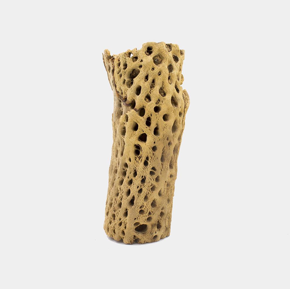 |
| cholla chunk |
Some detail about this process might prove useful to our future selves...
I found a decent photograph online and a web site that does "free" Raster-to-Vector conversions, if you have good images. I don't know how scammish this site is but, NoThanks-ing various pleading messages got me to where I could use it to convert images to vector outlines in DXF format.
https://online.rapidresizer.com/tracer.php
Strangely it worked well. I massaged the vector files to be useful to my purposes -- removing decorative and practical bits of material from some robot arms in order to slightly reduce their weight.
All the cactus files are here: My cholla files
- cholla2orig*.jpg are the original and P-shop massaged images.
- cholla3.* are the resulting vector data, and a jpg image thereof.
- cholla3ed.* are my editing of that data for use on the robot arms.
The non-orig JPG images are for reference purposes, and the .dxf files are what you need to load into a vector editing or cutter driving program. The DXF files may have bizarre scales -- the conversion came out to look like it was 64 feet wide -- so pay attention to the sizes... The .CAD files are the native format for the ancient drawing program I have.
Combining all the data, I cobbled together designs for five arms of different lengths using the different motors. So. Here. After all the measuring and converting is a motor with gears, mounted in a laser-cut robot-arm-like contraption:
 |
| arm with motor and gears |
And the DXF files: Long arm and Shorter arms. (Note that these files are preliminary and some finessing is still TBD.)
<EDIT 10/21/18> I think I fixed the files -- added spacers and other odd bits to the "shorter" one -- but still, check the mechanical hole sizes: Long arm and Shorter arms.</EDIT>
I cut the arms using the MSFe Zing laser cutter, which has some quirks. Chief among these for purposes of mechanical design is a somewhat variable kerf and a reasonable but unmentioned assumption about circular hole sizes. Fortunately the centering of holes is pretty spot on and the size assumption is that the drawn hole size is an ID -- so holes come out just about as you would expect. However, if one is cutting out round plugs, the kerf needs to be considered. Thus YMMV when using my files to try to make a copy of my arms, and test runs are advised. Also, judicious reaming and taping of holes is indicated during assembly.
More discussion of the design and gear linkage will follow...
Wednesday, October 10, 2018
Variations Too -- run up
And so, a couple months ago I came down with a (tiny) fit of organizing fever and cleared up a small portion of a pathway in (one of) my massively parallel parts storage areas. I found some crappy motors I had gotten (cheap) from a surplus place that I had attempted to make into a 2-d swinging robot arm, to make even some small progress on the big proposal.
They didn't work worth a damn:
 |
| picture of crappy motors |
But, out of curiosity, I found a sketch of my intentions in an old notebook from 2014 (where you can clearly see why I do not practice drawing and painting as a profession):
 |
| picture of robot arm crappy drawing |
I got to thinking that maybe I could re-start the whole project by actually spending money to get motors and components that might work. (Over this course I realized that I could spend $200 on oysters and gin and have a fine time with friends for an evening, or I could spend -- well, more, but in the ballpark -- on motors and gears, and get in a week or two of mostly enjoyable fiddling around before discovering that things weren't going to work; so, bang for buck over hours this is a way more economically efficient alternative.)
There ensued a couple weeks of web surfing trying to figure out what "hobby servo" motors to get, even though I already have about 50 random ones.
There are a number of vendors.
Each has around 100 choices.
The choices are mostly incommensurate.
Comparing across the sources, and sometimes within a single source, is problematic. Plus there are around 10 different output shaft "spline" configurations, that are often not even specified in the literature. I finally realized that I had to stick to one source (servocity.com, the high price spread, but has reasonably complete spec sheets). And this lead me to realize that I had only two choices of splines because they were the only two that had available matching gears to be attached. So I got an assortment of the highest power motors with the same matching splines, and a buncha gears:
 | |
| servo boxes |
Then, waiting on UPS Ground cheap(er) shipping, I thought I would just go ahead and design the mounting brackets and all. Thus I found that not even the motor manufacturer has mechanical drawings of their products (I did find one 3d rendering of one that I could rotate around in virtual space, which was kinda fun). Of course, one of the main things one wants to know when designing mounting plates for geared mechanisms is: How far is the output shaft from the mounting holes?
So. After the motors arrived I managed to measure and estimate the necessary and the gears seem to mesh OK. Just in case, here is my DXF drawing of the Hitek HS-225, HS-645, HS-755, and HS-805 motor mounts from which you may be able to extract relevant measurements. These are laid out to mesh two 32 pitch gears:
- 40 Tooth 1.250" Pitch diameter C1 Spline mount on the motor
- 20 Tooth 0.625" Pitch diameter plain bore on the mating arm
 |
| image of DXF for scale |
Variations More
Anyway. A few years ago the LA County Museum of Art (LACMA) re-started an Art and Technology program that had slipped under the waves in the early 70's. So I hacked and hewed a proposal to make a set of robot arms that Learned to Dance. I called the work Variations For as a pun on John Cage's, Variations IV, the canonical recording of which was made in LA in the mid-60's
Variations For Proposal
tldr; The arms solved the problem of knowing their own orientation and could just as well use the same sort of algorithms as my RoboCars to create a sequence of motions -- Teach Themselves to Dance -- AND could be influenced by viewer input via video. Plus the LACMA program was set up to put artists together with technological support -- which I could, certainly, use. That and money to pay for stuff...
Due to my obvious lack of Charm, Cachet, Credential, and Competence, they wisely declined my proposal. It was however a high point of my applying for things because I got BOTH an acknowledgement of receipt AND a politely encouraging rejection letter.
Funnily(?) enough. A couple years ago I ran across another artist who had subsequently applied for the same program with a proposal (in my loose interpretation) to make video game characters able to determine their own next moves rather than always having pre-programmed responses. Since he clearly was in possession of all the above 'C' qualities his project was accepted, and I noticed a recent announcement of some show of something in progress, up on which I did not follow.
N Variations on a Theme
Back in pre-history I had a job doing robotics research which lead me to make some small autonomous vehicles that, thanks to my friend Tori's support in showing something at her Dactyl space in Soho, developed a sequence of motions for themselves -- taught themselves a dance step.
Here's the whole presentation from a time when the internet sort of worked for video, which it now does in a completely differently-abled way (I think the video files are still there but they are in Quicktime which seems to have been disappeared):
ROBOCAR Collective
tldr; Each robot had a set of motions it could do -- forward, backward, and turns. It would pick a partner and each would select a motion and then adjudicate who's movement to execute. This would make that motion more likely to be selected, by both partners, in future situations. Then they would pick a new partner and repeat the exercise until, eventually, all five of the vehicles would be performing the same sequence. This was programmed using a Stochastic Finite State Automata, which is a fine state of affairs if you are not jargon enabled.
Unfortunately, I (they) had no way of knowing where each vehicle was and which way it was facing. So the net result still looked a bit of a jumble. But. Here is the U-Tub money shot from when "they" all happened to synchronize (at https://youtu.be/slfprpe848s):
I tried to fix the position insensitivity a couple times but eventually lost interest due to many of my pre-existing conditions.
Funny(?) aside. Now, ten or so years later, it appears that Urs Fischer has (hired folks to) solve this problem using a set of office chairs, as displayed at the Gagosian Gallery in Chelsea:
Gagosian -- Fischer -- Chairs
Sunday, May 10, 2015
Art Work
Following on from thought #1, Residue, this is thought #2 from my failed nap a couple weeks ago. If Art is always the useless bits leftover from cultural development, what comprises those bits right now? I'm not smart enough to jump the entire paradigm, but I do have this much:
Harking back to my whole schtick with the Prisoner's Dilemma where the "rational" solution -- defect -- is the "obvious" strategy which maximizes-reward and minimizes-risk over the short term. This optimizes well for evolutionary natural selection in a scarce and hostile environment, but results in a slightly less beneficial overall outcome -- versus cooperate -- for both parties over the long term.
And the long term is significant these days.
Thanks to over fitting, the Social Darwinists of the 19th century are no longer with us -- except in the guise of Libertarian economists -- but we still don't really think outside of the risk/reward box.
I recently attended an SFI talk by an evolutionary roboticist who, as an aside, complained that his evolved robots did not do so well in the long term. When I suggested that other fitness functions might be tried he pretty much dismissed the idea because they would be out-competed in the short term (in my own self-serving paraphrase of the interchange...).
But what if we try to do evolution with different utility functions?
If it's not Science, then what is it?
...Art...
Harking back to my whole schtick with the Prisoner's Dilemma where the "rational" solution -- defect -- is the "obvious" strategy which maximizes-reward and minimizes-risk over the short term. This optimizes well for evolutionary natural selection in a scarce and hostile environment, but results in a slightly less beneficial overall outcome -- versus cooperate -- for both parties over the long term.
And the long term is significant these days.
Thanks to over fitting, the Social Darwinists of the 19th century are no longer with us -- except in the guise of Libertarian economists -- but we still don't really think outside of the risk/reward box.
I recently attended an SFI talk by an evolutionary roboticist who, as an aside, complained that his evolved robots did not do so well in the long term. When I suggested that other fitness functions might be tried he pretty much dismissed the idea because they would be out-competed in the short term (in my own self-serving paraphrase of the interchange...).
But what if we try to do evolution with different utility functions?
- What's the best option for the common good?
- How can we all have the most fun?
- Can I be the best improvisational drummer in the ensemble?
- What would make the prettiest rainbows come out of my unicorn's butt?
If it's not Science, then what is it?
Thursday, April 30, 2015
Residue
(This is the result of not being able to nap after not being able to sleep before getting up too early...)
Art is the residue of culture on two levels.
In the first sense, art objects are the artifacts left over after all use-value has been extracted, i.e., when things have no further function they become Art. Pictures on a wall.
(Here the reader may insert an argument about design and craftsmanship and/or a counter argument about bad design.)
However in Level II of my alternate historicity, The Arts are the residue.
Lets say that Dark Ages newspapers had a monthly Arts section which covered everything from Hildegard von Bingen to Leonardo da Vinci.
Then later, during the Enlightenment, it became the Arts and Natural Philosophy page.
After which Science got it's own weekly publication, leaving us with the Art and Humanities magazine.
...und-so-weiter...
Until now: The Arts and Entertainment sunday supplement.
The point being that The Arts are always the residue of cultural ferment, calving off new areas of development. An interesting field of endeavor splits off and Art is left holding the spare parts bag.
Now. What if we split Entertainment off? After some bloody skirmishes, movies, TV, pop-music, yadayadayada, get their own section of the net, and The Arts gets the rest -- say Art and Culture. Opera, Symphony, Literature, Galleries, Museums, all the stuff that signifies sophistication to consummate 10%ers.
Then Culture can be excised. The historically significant art gallery and concert hall spectacles are all stuffed into convenient wallets and the surplus is renamed Arts and Ideas, where Ideas are what's left of late 20th century art.
So, ultimately Art is the leftover stew from whence Ideas bubble. When one of those New Ideas gains credence it becomes its own field leaving the unnecessary bits behind as The Arts. And without The Arts broth, New Ideas do not gestate.
Art is the residue of culture on two levels.
In the first sense, art objects are the artifacts left over after all use-value has been extracted, i.e., when things have no further function they become Art. Pictures on a wall.
(Here the reader may insert an argument about design and craftsmanship and/or a counter argument about bad design.)
However in Level II of my alternate historicity, The Arts are the residue.
Lets say that Dark Ages newspapers had a monthly Arts section which covered everything from Hildegard von Bingen to Leonardo da Vinci.
Then later, during the Enlightenment, it became the Arts and Natural Philosophy page.
After which Science got it's own weekly publication, leaving us with the Art and Humanities magazine.
Until now: The Arts and Entertainment sunday supplement.
The point being that The Arts are always the residue of cultural ferment, calving off new areas of development. An interesting field of endeavor splits off and Art is left holding the spare parts bag.
Now. What if we split Entertainment off? After some bloody skirmishes, movies, TV, pop-music, yadayadayada, get their own section of the net, and The Arts gets the rest -- say Art and Culture. Opera, Symphony, Literature, Galleries, Museums, all the stuff that signifies sophistication to consummate 10%ers.
Then Culture can be excised. The historically significant art gallery and concert hall spectacles are all stuffed into convenient wallets and the surplus is renamed Arts and Ideas, where Ideas are what's left of late 20th century art.
So, ultimately Art is the leftover stew from whence Ideas bubble. When one of those New Ideas gains credence it becomes its own field leaving the unnecessary bits behind as The Arts. And without The Arts broth, New Ideas do not gestate.
Monday, July 28, 2014
Feeling Abandoned (Meta) Analysis
My robot Feeling Abandoned (Stanley) was, by some reports, a hit of show during Currents 2014, c.f., He's Really Cute in the Dark.
The robot consists of two differential drive motors housed in a plastic toolbox with gripper arms on either end. It has sensors for the motor current, so it (sometimes) knows when it is stalled; and an accelerometer, so it (often) knows when it is bumped or lifted. A distance sensor on each end can "see" out to about 1.5m in a narrow band directly in front of the robot. The particular sensor I used only works down to just about the end of the gripper, so a bit of finagling was necessary to decide if a something was in gripping range. The grippers are also operated by motors and have position detecting switches and force sensors which can (usually) tell when they are open or closed. Unfortunately the force sensors are not good enough to detect if someone is fiddling with the grippers, but the bump sensor detects when someone pulls out of the gripper's hugging grasp. The 'bot can make a range of semi-musical sounds with a square wave generator and speaker and, per contemporary art/tech device requirements, there are flashing LEDs on top.
In operation he (sic) wanders around beeping tunelessly until he sees something that looks like a leg. When a leg is detected he approaches and tries to grab it. If the grab is successful he purrs for a while, or until the leg is pulled away, then he backs off and starts the search all over again.
Without a leg in sight he travels in a largish circle until he hits something whereupon he reverses direction. If he hits something shortly after changing direction he tries all of his possible motions in an attempt to escape. If he keeps hitting things he eventually decides that he is stuck, stops moving, and makes a call-for-help sound. If he is lifted and carried he makes a squealing sound until he is lowered to the ground again. When first started up or after being put back on the ground, he plays the Charge tune, known to football band members nation wide, before rolling off on his adventures.
Due to the under-powered drive mechanism he has some trouble with bumps in the road, e.g., taped-down power cables, and can easily become stuck. But in general he is able to traverse good portions of a gallery space without help in his hunt for things to hold onto.
I have found only two precedents for autonomous interactive robots in art environments:
With Stanley I, accidentally, struck an evocative balance between flaky sensors, weak motors, and anthropomorphism.
During the crowded opening I saw him sneak up and hug a number of unsuspecting legs to good effect. In the less populated times throughout the show many people, especially children, followed him around and tried to get him to interact.
The really interesting part was that, due to the flaky distance sensors, he could arbitrarily decide that he didn't have a leg to stand on and would just go back to wandering around. This was interpreted by many as "Not liking me." He did seem to take some time getting used to certain people before he would deign to give them a hug though. Also, when being tortured by (mostly) small children ordering, and often physically pushing and pulling, him around he went into his "escape" behavior and then shut down thinking he was stuck. Which he was.
I witnessed his non-hugging behaviors in two amusing instances. One day I came into the show space to have a look at the other work sans opening crowds and I heard his call-for-help sound. After some searching I found him stuck underneath the theater bleachers where he had wandered unsupervised. I had to crawl in to retrieve and release him back into the wild. On another evening the show organizers held a small fund-raising reception and wanted him to wander around during the meet'n'greet portion. But when it came time for speechifying his beeping was undesirable, so one of the staff members picked him up and carried him, squealing, out of the room. That got a good chuckle from the audience.
I noticed that Stanley was not treated as an art object, but rather, as the organizers said, a Mascot. I dutifully followed the crowd during a tour where artists present were asked to describe their work. When we crossed paths with Stanley he was introduced as the mascot but I was not asked to describe my "process". This is curious because Feeling Abandoned embodies an emotional message which is what many people find missing from techno-art. When I piped up with the full title the coin dropped for some of the tour members. Since I don't like using the appellation Art for my work and he did make some kind of small cross-over to life on his own terms I probably shouldn't whine to loudly.
The robot consists of two differential drive motors housed in a plastic toolbox with gripper arms on either end. It has sensors for the motor current, so it (sometimes) knows when it is stalled; and an accelerometer, so it (often) knows when it is bumped or lifted. A distance sensor on each end can "see" out to about 1.5m in a narrow band directly in front of the robot. The particular sensor I used only works down to just about the end of the gripper, so a bit of finagling was necessary to decide if a something was in gripping range. The grippers are also operated by motors and have position detecting switches and force sensors which can (usually) tell when they are open or closed. Unfortunately the force sensors are not good enough to detect if someone is fiddling with the grippers, but the bump sensor detects when someone pulls out of the gripper's hugging grasp. The 'bot can make a range of semi-musical sounds with a square wave generator and speaker and, per contemporary art/tech device requirements, there are flashing LEDs on top.
In operation he (sic) wanders around beeping tunelessly until he sees something that looks like a leg. When a leg is detected he approaches and tries to grab it. If the grab is successful he purrs for a while, or until the leg is pulled away, then he backs off and starts the search all over again.
Without a leg in sight he travels in a largish circle until he hits something whereupon he reverses direction. If he hits something shortly after changing direction he tries all of his possible motions in an attempt to escape. If he keeps hitting things he eventually decides that he is stuck, stops moving, and makes a call-for-help sound. If he is lifted and carried he makes a squealing sound until he is lowered to the ground again. When first started up or after being put back on the ground, he plays the Charge tune, known to football band members nation wide, before rolling off on his adventures.
Due to the under-powered drive mechanism he has some trouble with bumps in the road, e.g., taped-down power cables, and can easily become stuck. But in general he is able to traverse good portions of a gallery space without help in his hunt for things to hold onto.
I have found only two precedents for autonomous interactive robots in art environments:
- Norman White, Helpless Robot -- asked visitors to move it around;
- Simon Penny, Petit Mal -- found and approached visitors;
- Autonomous -- not remote controlled;
- Interactive -- multiple behaviors related to audience members;
With Stanley I, accidentally, struck an evocative balance between flaky sensors, weak motors, and anthropomorphism.
During the crowded opening I saw him sneak up and hug a number of unsuspecting legs to good effect. In the less populated times throughout the show many people, especially children, followed him around and tried to get him to interact.
The really interesting part was that, due to the flaky distance sensors, he could arbitrarily decide that he didn't have a leg to stand on and would just go back to wandering around. This was interpreted by many as "Not liking me." He did seem to take some time getting used to certain people before he would deign to give them a hug though. Also, when being tortured by (mostly) small children ordering, and often physically pushing and pulling, him around he went into his "escape" behavior and then shut down thinking he was stuck. Which he was.
I witnessed his non-hugging behaviors in two amusing instances. One day I came into the show space to have a look at the other work sans opening crowds and I heard his call-for-help sound. After some searching I found him stuck underneath the theater bleachers where he had wandered unsupervised. I had to crawl in to retrieve and release him back into the wild. On another evening the show organizers held a small fund-raising reception and wanted him to wander around during the meet'n'greet portion. But when it came time for speechifying his beeping was undesirable, so one of the staff members picked him up and carried him, squealing, out of the room. That got a good chuckle from the audience.
I noticed that Stanley was not treated as an art object, but rather, as the organizers said, a Mascot. I dutifully followed the crowd during a tour where artists present were asked to describe their work. When we crossed paths with Stanley he was introduced as the mascot but I was not asked to describe my "process". This is curious because Feeling Abandoned embodies an emotional message which is what many people find missing from techno-art. When I piped up with the full title the coin dropped for some of the tour members. Since I don't like using the appellation Art for my work and he did make some kind of small cross-over to life on his own terms I probably shouldn't whine to loudly.
Subscribe to:
Comments (Atom)